LRK345-20-xx |
this page will be kept for educational reason. |

By Jochen and Peter, January 2002
Kit principles of the LRK345-20
Many of us do not have the possibility to manufacture the turned parts themselves, although they would very much like to build an LRK345-20. The remaining parts can be obtained elsewhere and one can then wind the stator as desired. Because the motor is designed to simply unscrew, one can do two or more stators (cheap), wind differently and use with the same rotor.
Construction
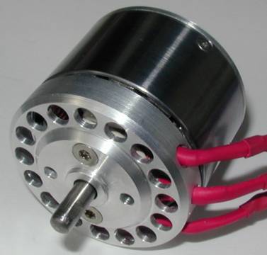
We designed and built our own Torquemax. It is strong and adapted to everyday use, easily converts 400W (600W for short periods) and the most important for us: it can be mounted to the firewall like every other engine.
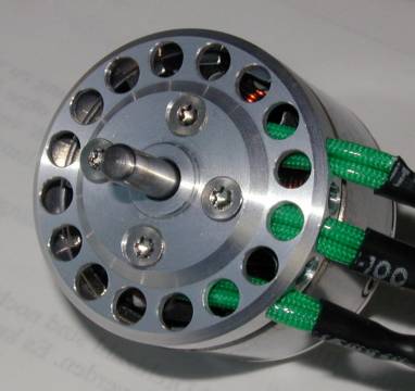
Because of the need for the rotor to spin behind the firewall, the drive shaft must go trough the stator block. In order to withstand heavy loads a 5mm shaft (hardened steel) was used, and the distance between the two ball bearings was maximized without changing the overall length. This cannot be done satisfactorily with the original Torquemax design a smaller distance between bearings means higher forces on the same, reducing life expectancy and increasing free play between rotor and stator (vibrations). The bearing size was also increased, in spite of the additional weight (8g).The rear bearing must take the axial load of the propeller in use and therefore a larger size (16x5x5) to the front one (11x5x4) was preferred. Another important property was on our wish list: The motor should come apart easily, this way construction changes can be made any time and repairs can be done by simply exchanging the damaged parts. The only things that need to be glued are the magnets (inside the rotor). The solution was the Design of the stator that bolts together, through which the drive shaft goes forward. Since the propeller pulls the shaft forward, pulling the rotor over the stator even more, there is no need to secure the shaft axially other than to the rotor. No fear, the rotor cannot accidentally slide off backwards, the rare earth magnets as way to strong for this to happen. Mounting a motor constructed this way behind the firewall has yet another (unwanted, but welcome) advantage: Should the plane get hit on the nose (bad landing, transport) all that can happen is that the rotor/shaft assembly travels backwards a bit (damped by the magnets) eventually until the propeller yoke hits the firewall, which will then absorb the forces while the motor remains undamaged.
Finally a front shield was added to protect the connections and the winding.
Turned parts set
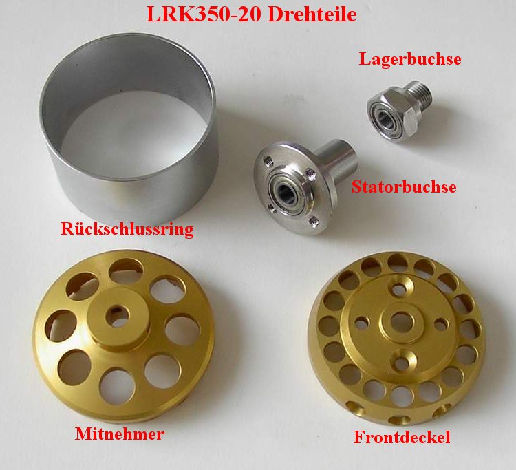
We have asked a professional company in Germany to manufacture the necessary turned parts, and we got an offer for (high quality) CNC turned parts as can be seen in the picture below.
Remaining parts
there are no remaining parts
with order at
www.torcman.com
Remaining work
It must be said that a good deal of technical proficiency is needed to finish the construction of the motor. More infos can generally be found on the web, like here for instance: LRK-Diskussionsforum, where all construction techniques are discussed (albeit in German).
We will translate our "contruction instruction" soon.
The calculation of the number of turns needed for a specific application can be found on my homepage, or I can provide this service for a small fee. The results of these calculations are typically accurate to about 3%.
Ordering a kit
Every kit will be delivered with extensive documentation, instructions for the gluing of the magnets and the winding of the stator, so even a beginner should be able to build his motor accurately and professionally.
Please send an email to
Pictures
Actual models
|
|
|
Old models
